After my talk at Pacificon a few months ago, several people reached out to me about setting up a radiosonde receiving station at their house. They specifically had questions about the antenna and LNA, and after answering the same question a few times I decided to do a post about this topic.
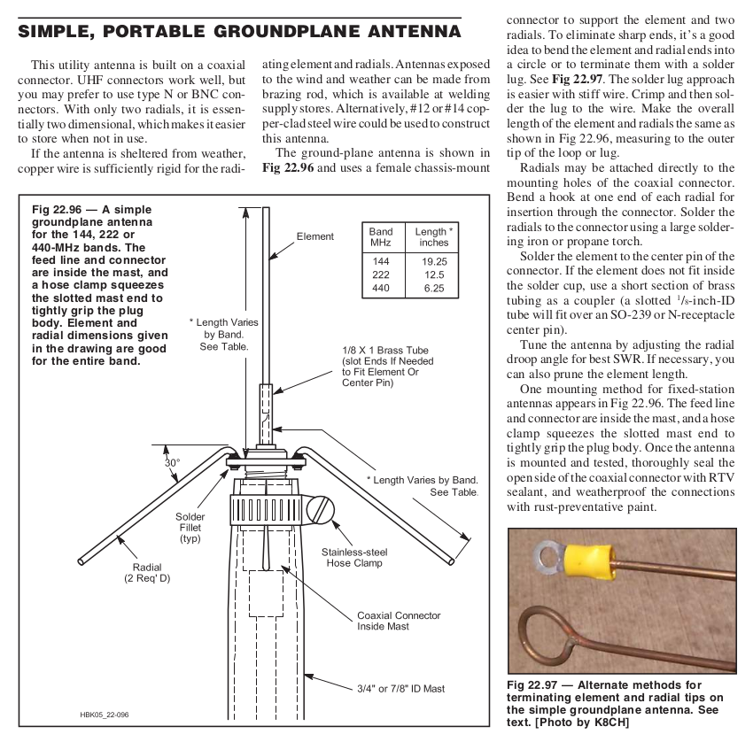
Building a 1/4 wave ground plane antenna is very easy to do. The overall design is simple, with a vertical element surrounded by a ground plane consisting of two or four wires bent down. Here are the dimensions for the VHF/UHF amateur radio bands (from the ARRL Handbook), but these dimensions can be scaled to any frequency.
There are many online calculators that will give you the approximate dimensions for the elements, but I usually use M0KUD's calculator. Whenever you are making antennas, always cut your elements a bit longer (maybe 20%) than the calculation says, then trim them during tuning.
Use any type of wire for the elements. I use standard 14-gauge solid copper wire because it's easy to get from the hardware store, it's somewhat rigid, and easy to solder. It doesn't matter if the wire has insulation, you can buy bare wire or strip it off if you want. Thicker gauge wire means wider bandwidth.

As you can see in the pic above, the elements were originally much shorter. This was to receive radiosondes from Oakland Airport that I thought were transmitting on 1680 MHz, but then I found that the actual transmit frequency was 403 MHz, so I lap-soldered more wire on to bring the resonant frequency down.
The only "special" part you'll need to order (or scavenge) is a female chassis/panel mount solder connector. I prefer using N connectors when constructing antennas, as they are much bigger than SMA connectors and therefore easier to solder with my fat soldering iron tip and fat fingers. I would discourage the use of UHF connectors (PL-259/SO-239), as they are very lossy above 100 MHz.
One word of warning: Don't buy cheap no-name connectors from the internet. While they appear to be a good deal (5 connectors for only $10!), the reason they are cheap is because they use cheap dielectric material (such as delrin) that melts below the solder temperature. So in the process of soldering the center pin, the insulating material will melt and dribble out, and the connector will be ruined. Only buy a connector that has a datasheet that specifies a teflon (PTFE) dielectric.
Another pro tip: When soldering connectors, always thread the connector onto something, like a cable or another connector. The opposite-gender connector will add thermal mass, slowing the rate at which the everything heats up, and also ensures the center pin stays aligned and fixed in place if the dielectric becomes soft. The only downside is that it takes a bit longer to solder.
Measuring and Tuning
The only downside to building your own antenna is that you will need a way to measure the resonant frequency and tune it to your desired frequency. The easiest way is to use an antenna analyzer or network analyzer. Expensive test equipment is not necessary (but so much fun to play with!), as there are several flavors of NanoVNAs on the market now which perform decently up through 1 GHz. While these are relatively cheap, some work better than others, and some of the cheap Chinese knockoffs don't work at all. Caveat emptor!
Even if you don't have an antenna or network analyzer, someone in your local ham club or radiosonde community either owns one or has access to one. I'm sure they will be delighted to help you out with measuring antennas.
Here's the S11 return loss measurement for my homemade quarter wave ground plane radiosonde receiving antenna at home. The return loss is around 22 dB, which corresponds to an SWR of 1.17:1. Pretty good!

I consider anything better than 10 dB return loss (SWR of 2:1) to be a good antenna. There is a formula to convert return loss into SWR, but since everything I do is 50 ohms I just use a table. More return loss is better, meaning that more energy is being radiated out into the air (which is what we want). In this plot you can also see the 3rd harmonic up around 1200 MHz, with a return loss of around 12 dB.
Weatherproofing
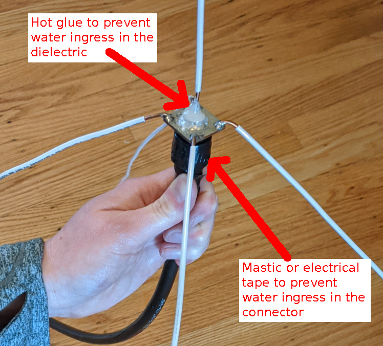
Since this antenna will be outside on a mast, waterproofing the antenna is required to prevent water intrusion in the coaxial cable. The antenna is cheap enough and easily repaired if it is damaged by the elements, but the coax is expensive, especially for long runs. Water in the coax cable will slowly degrade the coax, potentially shorting things out and changing impedances. But it's a difficult problem to diagnose because problems are only apparent after it's been raining for a while, then disappear after the sun comes out for a day or two.
The antenna top (solder) side can be hot glued, and the connector side (bottom) should be sealed with mastic, such as 3M 2228, or electrical tape. The individual elements do not need to be sealed in any way. Eventually copper starts to turn green, but it has no effect on RF performance.
403 MHz Radiosonde Antenna
Here in the San Francisco Bay Area, the local radiosondes transmit around 403 MHz. This is slightly below the 70cm amateur radio band, so for a while I used a Diamond X-50NA at my home in San Francisco. While it's a great dual-band amateur radio antenna, it performs very poorly at 403 MHz. This antenna isn't resonant at this frequency, and the gain is towards the horizon (where the radiosondes aren't).
I built a quarter-wave wave ground plane for 403 MHz, with the elements about 18 cm (7 inches) long, with radials that are about 15% longer.
Amateur Radio/AIS Antenna
I also built a 145 MHz amateur band antenna for receiving Amateur satellites. And since marine radio AIS frequencies are just a bit higher at 160 MHz, I tried to center the resonant frequency at around 152 MHz.
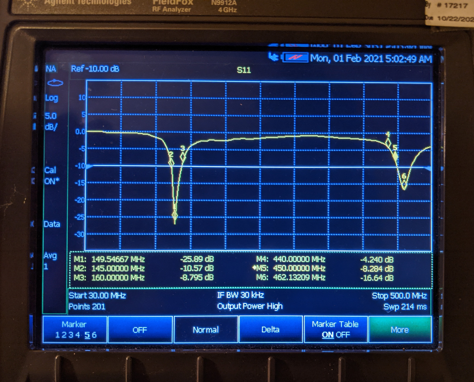
As you can see, I got it pretty close! Return loss in the Amateur satellite band at 145 MHz is 10.5 dB, and 8.8 dB in the AIS band.
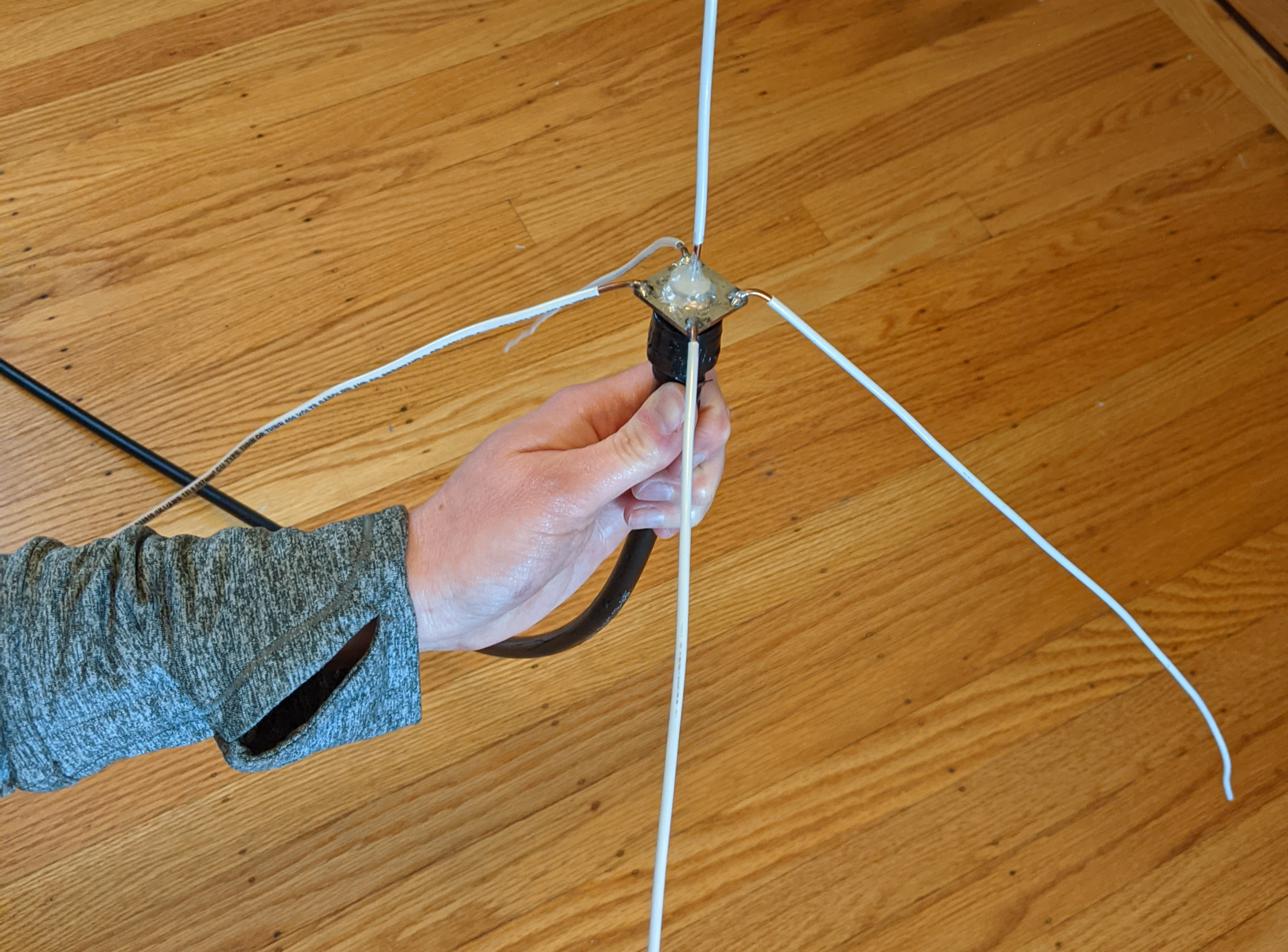
This quarter wave ground plane antenna is pretty big! The elements are about 50 cm (20 inches) long, which is about the longest you can make them with standard 14-gauge copper and still keep it's shape. Bigger than this and the ground plane elements droop considerably and blow around in the wind. This doesn't affect performance too much, it just looks bad.